Setting up the clock frequency
Next step would be to test a sequential circuit and make sure simulation works. I will try to implement a 32bit counter in verilog and try to get some feedback about the values it holds using a few LEDs.
Default net type
First thing is to tell Verilog to be as strict as possible when trying to guess the types of my wires/regs. By default Verilog does not require me to declare signals before I use them. By default any undeclared one will be a wire. Solution to this problem is a directive called default_nettype and I will need to set it to none:
`default_nettype none // will error if there are undeclared nets
Please note that the first character is not the regular single quote but the back-quote (usually found on the same key as “~”, to the left of “1”).
Simple counter
With this out of the way let’s start thinking about how to implement a counter. Until now I used wire and “assign” statement to assign states (values) to them. I used combinatorial logic (all statements executed at the same time) and this is clearly not enough because for a counter be incremented it needs to remember its previous value.
Verilog offers the register type for this : reg. This is implemented with either a latch or a flip-flop (FF) and it represents data storage elements. Declaring works like it does for wires:
reg counter;
This declares a 1 bit register named counter. If size is not specified, verilog defaults to 1 and I will need a larger register than this 1 bit-wide one. This would be the proper way of declaring a 32 bit register:
reg [31:0] counter;
This way of declaring the size is using little-endian convention: starting with 0 at the rightmost bit. This bit is also named “least significant bit” or LSB. Please remember this is just a convention, it determines how the data will read. I could have just as easily use big-endian by declaring the vector [0:31] but I am used to little-endian processors so I will stick with this. Consistency is also important, please do not mix these! You can, verilog allows it but don’t do it or a kitten will die.
To increment the counter I need a way to split the time in regular intervals: a clock.
`default_nettype none

module counter (
    input CLK,
    output wire LED_GREEN4,
    output wire LED_GREEN5 );

reg [31:0] counter;

assign LED_GREEN5 = counter[4];
assign LED_GREEN4 = counter[2];

always @(posedge CLK) begin
    counter <= counter + 1;
end

endmodule
My module has one input which is the clock (CLK) and two outputs which are two LEDs. I am assigning bits 2 and 4 to the LEDs to see some feedback while the counter increments.
I am using a sequential block triggered whenever the clock has a rising edge. The @() construct contains the sensitivity list: signals which can trigger “execution” of that always block.
I am incrementing the counter using a non-blocking assignment. Usage of blocking or non-blocking assignments is a design-dependent decision. In my opinion the core difference between these two is:
- blocking assignments need to happen one after the other fully (evaluating each actual value being assigned and assigning it).
- non-blocking assignments happen concurently after all the right-side values have been evaluated in the whole block.
I almost never use blocking assignments because it creates problems with simulators.
I saved this file as counter.v
iVerilog compiles this just fine but I need a testbench. I cannot just use the one from the previous article because now I need to provide a clock. Here is what I came up with:
module test;

reg clk = 0;
wire led1;
wire led2;

    initial
        begin
            $dumpfile("complete.vcd");
            $dumpvars(0, test);
            #1000 $finish;
        end

    always #1 clk = !clk;

    counter cnt (clk, led1, led2);

endmodule
I saved this as test.v and then I ran the simulation.
iverilog test.v counter.v -o counter
vvp counter
gtkwave complete.vcd
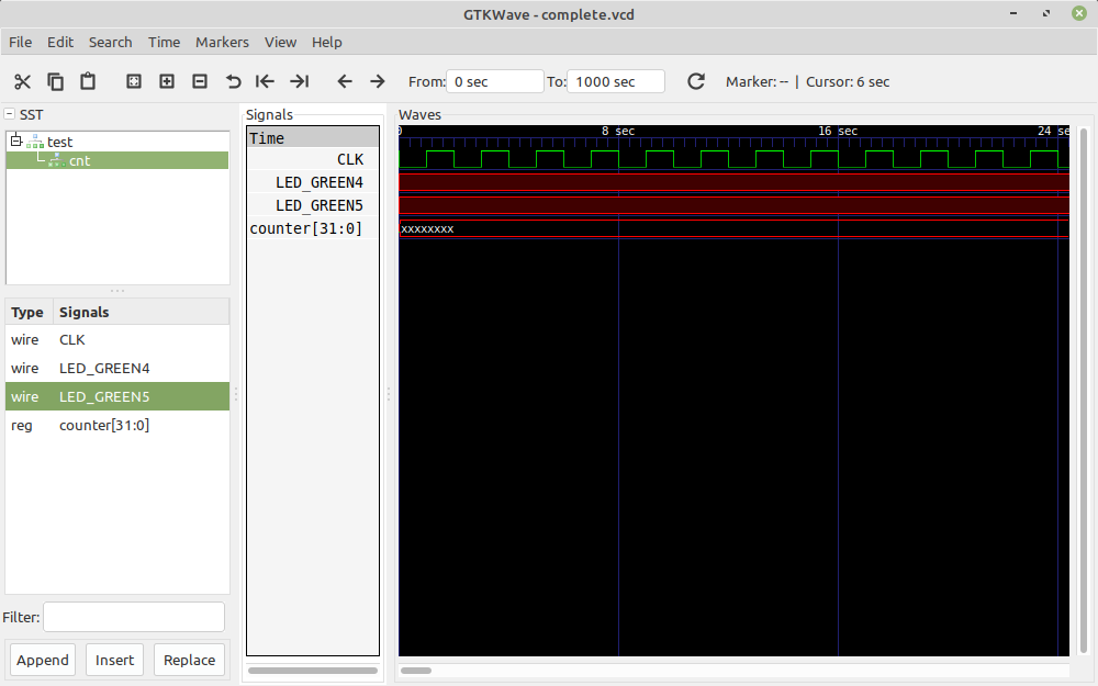
Hmmm, something is wrong. Counter has a value of xxxxxx which means undetermined or unknown value. Why is that ? Well, pretty simple, nowhere in my code I set up an initial value for it. To increment its value it has to start from something, right ?
Counter with reset
The easiest way of doing this is using an initial block and giving it a value like this:
initial begin
    counter = 0;
end
I can also add the initial value in the declaration phase which will have the same effect:
reg [31:0] counter = 0;
This would work even with FPGAs but not with ASICs. In FPGAs there is the bitstream which can be used to set initial values but ASICs don’t have this luxury.
The proper way to do this would be with a reset signal. I define another input named RESET which will be driven from the testbench. For the lolz I made it active-low:
`default_nettype none

module counter (
    input CLK,
    input RESET,
    output wire LED_GREEN4,
    output wire LED_GREEN5 );

reg [31:0] counter;

assign LED_GREEN5 = counter[4];
assign LED_GREEN4 = counter[2];

always @(posedge CLK or negedge RESET) begin
    if (RESET == 0)
        counter <= 0;
    else
        counter <= counter + 1;
end

endmodule
I added another signal in the sensitivity list which is triggered when it transitions from high to low (1 to 0). Because there are multiple triggering signals the code needs to be modified to clarify which ones affect which part of the block. I do this using a regular if/else construct while trying to make sure I don’t left out any possible case/combination of triggering values. You can read this as “If reset is active then set counter to 0. If reset is not active then it must be the clock and counter increments”.
Here is the testbench to go with it:
module test;

reg clk = 0;
reg reset = 1;
wire led1;
wire led2;

    initial
        begin
            $dumpfile("complete.vcd");
            $dumpvars(0, test);
            #2 reset = 0;
            #4 reset = 1;
            #1000 $finish;
        end

    always #1 clk = !clk;

    counter cnt (clk, reset, led1, led2);

endmodule
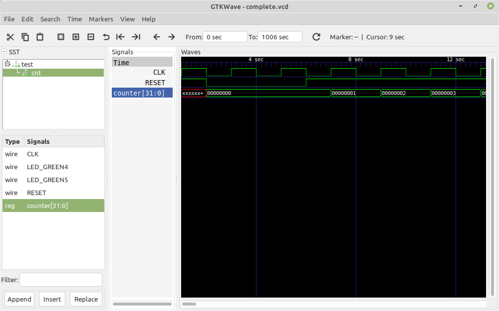
In this testbench I set up the initial value of reset to 1 and then I toggle it to 0 and back to 1. As you can see until that point counter has an unknown value but after reset goes back to 1 counter starts at 0 and increments every clock.
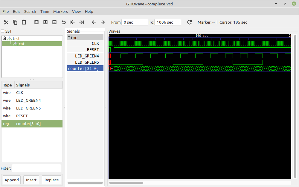
Pretty good, exactly what I expected. Here is how the LEDs get assigned and as expected one pulses much faster than the other one:
Let’s make it work on the FPGA
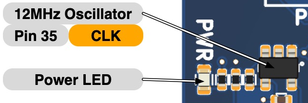
Icebreaker board has a 12MHz clock connected to pin 35 of the FPGA.
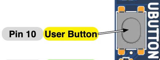
I am also going to use the user button which is connected to pin 10 as reset signal because it is already wired as “active low”
This means the new icebreaker.pcf file can be updated as follows:
set_io LED_USR_RED  11
set_io LED_USR_GRN  37
set_io LED_RED      26
set_io LED_GREEN2   27
set_io LED_GREEN3   25
set_io LED_GREEN4   23
set_io LED_GREEN5   21

set_io BTN_USR      10
set_io BTN_1        20
set_io BTN_2        19
set_io BTN_3        18

set_io CLK          35
I saved the counter.v file as fpgacounter.v and modified the module name from “counter” to “top” (remember, top in verilog is like main in C).
Because I used the proper names for the LEDs I can go ahead and reuse the ninja build script from the previous article with only a slight filename modification since the source file now is named fpgacounter.v.
rule synthesize
  command = yosys -ql yosys-output.log -p 'synth_ice40 -top top -json $out' $in

rule placeroute
  command = nextpnr-ice40 --pcf-allow-unconstrained --up5k --package sg48 --json $in --pcf icebreaker.pcf --asc $out

rule pack
  command = icepack $in $out

rule program
  command = iceprog $in

build fpgacounter.json: synthesize fpgacounter.v

build fpgacounter.asc: placeroute fpgacounter.json

build fpgacounter.bin: pack fpgacounter.asc

build prog: program fpgacounter.bin
This is the FPGA routing result, the design uses 9 logic elements out of 5280:
Info: Device utilisation:
Info:            ICESTORM_LC:     9/ 5280     0%
Info:           ICESTORM_RAM:     0/   30     0%
Info:                  SB_IO:     4/   96     4%
Info:                  SB_GB:     1/    8    12%
Info:           ICESTORM_PLL:     0/    1     0%
Info:            SB_WARMBOOT:     0/    1     0%
Info:           ICESTORM_DSP:     0/    8     0%
Info:         ICESTORM_HFOSC:     0/    1     0%
Info:         ICESTORM_LFOSC:     0/    1     0%
Info:                 SB_I2C:     0/    2     0%
Info:                 SB_SPI:     0/    2     0%
Info:                 IO_I3C:     0/    2     0%
Info:            SB_LEDDA_IP:     0/    1     0%
Info:            SB_RGBA_DRV:     0/    1     0%
Info:         ICESTORM_SPRAM:     0/    4     0%
Result of yosys parsing is pretty simple:

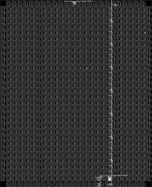
Result of ICE40 synthesis looks quite complicated and it is very hard to follow:

Graphically it looks like this:
Hardware test
Programming the board works as expected but the LEDs are continuously lit. Because I am linking them to bits 2 and 4 of the counter and the clock is 12MHz they switch too fast. I changed them to mirror bits to 20 and 22 from the counter and now I get the blinking pattern I expected. I am sorry if the quality of the video is not too great but it shows what’s important:
I didn’t show on the video but the reset works as expected too, if I push the button the LEDs go off because counter keeps being reset to 0.
Github link
All the sources are available on Github at the address:
https://github.com/z80-ro/verilog-tests/tree/master/01_clock_frequency